

TOLONG BACA DENGAN DETAIL !
Siapkan alat dan bahan :
- Minimum sytem atmega 8
- Variable resistor 10k
- Lcd 16x2
- Motor dc (2)
- IC L293D
- Push button (2)
- Kabel jumper disesuaikan
- Breadboard
- Kabel usb
- Laptop
- Software codevision avr
- Download simulasi proteus
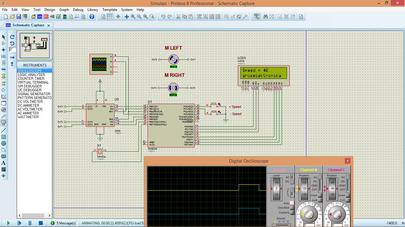
1. Sambungkan semua komponen sesuai dengan gambar atau bisa kalian coba dulu pada software proteus isis
 CATATAN !
a. Pastikan setting software sudah sesuai
b. Pastikan pin PWM terdapat pada PORTB.1 dan PORTB.2 pada atmega 8
c. Pastikan settingan crystal menggunakan 12 Mhz
d. Timer 1 dan timer 2 sama saja tinggal kalian pilih salah satu
a. Pastikan setting software sudah sesuai
b. Pastikan pin PWM terdapat pada PORTB.1 dan PORTB.2 pada atmega 8
c. Pastikan settingan crystal menggunakan 12 Mhz
d. Timer 1 dan timer 2 sama saja tinggal kalian pilih salah satu
2. Buat program seperti dibawah ini pada software codevisionavr,apabila ada yang belum tau cara menggunakan software codevision avr bisa baca disini
Sebelum membuat program,kalian setting dulu pada codevision avr dan proteus seperti ini
Dengan menggunakan TIMER 1

Dengan menggunakan TIMER 2

Display setting


4. Download program .hex (hasil compile) pada minimum sistem menggunakan usb asp baca disini,bila menggunakan simulasi tinggal kalian masukan file .hexnya ke dalam ic baca disini
Theory Timer
Untuk theory lebih lanjut kalian baca disini dan disini
Instruction
Jika kalian membuatnya pada simulasi,kalian coba run ,jika kalian ingin menambah kecepatan tekan tombol + speed,dan jika kalian ingin menurunkan kecepatan kalian tekan tombol - speed,lihat perubahan signal pwm pada osciloscop dan lcd
Development
bisa kalian kembangkan,contohnya membuat robot line follower ketika robot berberlok kalian bisa atur kecepatan motornya
Sebelum membuat program,kalian setting dulu pada codevision avr dan proteus seperti ini
Dengan menggunakan TIMER 1

Dengan menggunakan TIMER 2

Display setting


/*******************************************************
This program was created by the
CodeWizardAVR V3.12 Advanced
Automatic Program Generator
© Copyright 1998-2014 Pavel Haiduc, HP InfoTech s.r.l.
http://www.hpinfotech.com

Project : Akses PWM
Version :
Date    : 6/30/2016
Author  : Fickry Muhammad
Company : PT LEN
Comments:


Chip type               : ATmega8
Program type            : Application
AVR Core Clock frequency: 12.000000 MHz
Memory model            : Small
External RAM size       : 0
Data Stack size         : 256
*******************************************************/

#include <mega8.h>
#include <stdio.h>
#include <delay.h>

// Alphanumeric LCD functions
#include <alcd.h>

#define incr_speed PINC.0
#define decr_speed PINC.1

#define motor_1_forward PORTB.0
#define motor_1_reverse PORTB.3

#define motor_2_forward PORTB.4
#define motor_2_reverse PORTB.5


// Declare your global variables here

int speed = 0;
char buffer[20];

void main(void)
{
// Declare your local variables here

// Input/Output Ports initialization
// Port B initialization
// Function: Bit7=Out Bit6=Out Bit5=Out Bit4=Out Bit3=Out Bit2=Out Bit1=Out Bit0=Out
DDRB=(1<<DDB7) | (1<<DDB6) | (1<<DDB5) | (1<<DDB4) | (1<<DDB3) | (1<<DDB2) | (1<<DDB1) | (1<<DDB0);
// State: Bit7=0 Bit6=0 Bit5=0 Bit4=0 Bit3=0 Bit2=0 Bit1=0 Bit0=0
PORTB=(0<<PORTB7) | (0<<PORTB6) | (0<<PORTB5) | (0<<PORTB4) | (0<<PORTB3) | (0<<PORTB2) | (0<<PORTB1) | (0<<PORTB0);

DDRC.0  = 0;
PORTC.0 = 1;

DDRC.1  = 0;
PORTC.1 = 1;

// Timer/Counter 0 initialization
// Clock source: System Clock
// Clock value: Timer 0 Stopped
TCCR0=(0<<CS02) | (0<<CS01) | (0<<CS00);
TCNT0=0x00;

// Timer/Counter 1 initialization
// Clock source: System Clock
// Clock value: 46.875 kHz
// Mode: Ph. correct PWM top=0x03FF
// OC1A output: Non-Inverted PWM
// OC1B output: Non-Inverted PWM
// Noise Canceler: Off
// Input Capture on Falling Edge
// Timer Period: 43.648 ms
// Output Pulse(s):
// OC1A Period: 43.648 ms Width: 32.725 ms
// OC1B Period: 43.648 ms Width: 0 us
// Timer1 Overflow Interrupt: Off
// Input Capture Interrupt: Off
// Compare A Match Interrupt: Off
// Compare B Match Interrupt: Off
TCCR1A=(1<<COM1A1) | (0<<COM1A0) | (1<<COM1B1) | (0<<COM1B0) | (1<<WGM11) | (1<<WGM10);
TCCR1B=(0<<ICNC1) | (0<<ICES1) | (0<<WGM13) | (0<<WGM12) | (1<<CS12) | (0<<CS11) | (0<<CS10);
TCNT1H=0x00;
TCNT1L=0x00;
ICR1H=0x00;
ICR1L=0x00;
OCR1AH=0x02;
OCR1AL=0xFF;
OCR1BH=0x00;
OCR1BL=0x00;

// Timer/Counter 2 initialization
// Clock source: System Clock
// Clock value: Timer2 Stopped
// Mode: Normal top=0xFF
// OC2 output: Disconnected
ASSR=0<<AS2;
TCCR2=(0<<PWM2) | (0<<COM21) | (0<<COM20) | (0<<CTC2) | (0<<CS22) | (0<<CS21) | (0<<CS20);
TCNT2=0x00;
OCR2=0x00;

// Timer(s)/Counter(s) Interrupt(s) initialization
TIMSK=(0<<OCIE2) | (0<<TOIE2) | (0<<TICIE1) | (0<<OCIE1A) | (0<<OCIE1B) | (0<<TOIE1) | (0<<TOIE0);

// External Interrupt(s) initialization
// INT0: Off
// INT1: Off
MCUCR=(0<<ISC11) | (0<<ISC10) | (0<<ISC01) | (0<<ISC00);

// USART initialization
// USART disabled
UCSRB=(0<<RXCIE) | (0<<TXCIE) | (0<<UDRIE) | (0<<RXEN) | (0<<TXEN) | (0<<UCSZ2) | (0<<RXB8) | (0<<TXB8);

// Analog Comparator initialization
// Analog Comparator: Off
// The Analog Comparator's positive input is
// connected to the AIN0 pin
// The Analog Comparator's negative input is
// connected to the AIN1 pin
ACSR=(1<<ACD) | (0<<ACBG) | (0<<ACO) | (0<<ACI) | (0<<ACIE) | (0<<ACIC) | (0<<ACIS1) | (0<<ACIS0);
SFIOR=(0<<ACME);

// ADC initialization
// ADC disabled
ADCSRA=(0<<ADEN) | (0<<ADSC) | (0<<ADFR) | (0<<ADIF) | (0<<ADIE) | (0<<ADPS2) | (0<<ADPS1) | (0<<ADPS0);

// SPI initialization
// SPI disabled
SPCR=(0<<SPIE) | (0<<SPE) | (0<<DORD) | (0<<MSTR) | (0<<CPOL) | (0<<CPHA) | (0<<SPR1) | (0<<SPR0);

// TWI initialization
// TWI disabled
TWCR=(0<<TWEA) | (0<<TWSTA) | (0<<TWSTO) | (0<<TWEN) | (0<<TWIE);

// Alphanumeric LCD initialization
// Connections are specified in the
// Project|Configure|C Compiler|Libraries|Alphanumeric LCD menu:
// RS - PORTD Bit 0
// RD - PORTD Bit 1
// EN - PORTD Bit 2
// D4 - PORTD Bit 4
// D5 - PORTD Bit 5
// D6 - PORTD Bit 6
// D7 - PORTD Bit 7
// Characters/line: 16
lcd_init(16);

while (1)
      {
      // Place your code here

      motor_1_reverse = 1;
      motor_2_reverse = 1;

      OCR1A = speed;
      OCR1B = speed;

        if (incr_speed == 0)
        {
        speed = speed + 10;
        delay_ms(200);
        }

        if (decr_speed == 0)
        {
        speed = speed - 10;
        delay_ms(200);
        }

        if (speed <= 0) speed = 0;

      sprintf(buffer,"Speed = %02d",speed);
      lcd_gotoxy(0,0);
      lcd_puts(buffer);
      lcd_gotoxy(0,1);
      lcd_putsf("aruselektronika");

      delay_ms(100);
      }
}
3. Compile project pada software cvavr,apabila tidak terjadi error lanjut dengan proses upload atau build all project files 4. Download program .hex (hasil compile) pada minimum sistem menggunakan usb asp baca disini,bila menggunakan simulasi tinggal kalian masukan file .hexnya ke dalam ic baca disini
Theory Timer
Timer0
Mode Phase Correct PWM
Foc0 = Fosc/(N*512)
D = (OCR0/255)*100%
Mode Fast PWM
Foc0 = Fosc/(N*256)
D = (OCR0/255)*100%
Mode Phase Correct PWM
Foc0 = Fosc/(N*512)
D = (OCR0/255)*100%
Mode Fast PWM
Foc0 = Fosc/(N*256)
D = (OCR0/255)*100%
Dimana:
Foc0 = Frekuensi output OC0
N = Skala clock (mempunyai nilai 1, 8, 64, 256 dan 1024)
D = Duty cycle
Fosc = Frekuensi clock kristal yang digunakan
Foc0 = Frekuensi output OC0
N = Skala clock (mempunyai nilai 1, 8, 64, 256 dan 1024)
D = Duty cycle
Fosc = Frekuensi clock kristal yang digunakan
Timer1
Mode Phase Correct PWM
Foc1a = Fosc/(2*N*TOP)
Foc1b = Fosc/(2*N*TOP)
D = (OCR1X/TOP)*100%
Foc1a = Fosc/(2*N*TOP)
Foc1b = Fosc/(2*N*TOP)
D = (OCR1X/TOP)*100%
Mode Fast PWM
Foc1a = Fosc/(N*(1+TOP))
Foc1b = Fosc/(N*(1+TOP))
D = (OCR1X/TOP)*100%
Foc1a = Fosc/(N*(1+TOP))
Foc1b = Fosc/(N*(1+TOP))
D = (OCR1X/TOP)*100%
Dimana:
Foc1a = Frekuensi output OC1A
Foc1b = Frekuensi output OC1B
N = Skala clock (mempunyai nilai 1, 8, 64, 256 dan 1024)
D = Duty cycle
Fosc = Frekuensi clock kristal yang digunakan
TOP = nilai maksimum counter (TCNT1), TOP mempunyai 3 buah nilai untuk kedua mode tersebut yaitu 8 bit (FF), 9 bit (1FF) dan 10 bit (3FF)
Sekarang saya akan membuat aplikasi membangkitkan sinyal
PWM dengan periode 20 ms dengan duty cycle 75%, menggunakan Timer1 10 Bit
Mode Fast PWM.
Dengan menggunakan kristal 12 Mhz, N = 256 dan TOP = 10
bit = 3FF = 1023
Maka akan didapat frekuensi output (Foc1x) sebesar 45,77
Hz atau jika diubah kedalam peroide 21,8 ms ≈ 20 ms
Untuk Duty cycle:
D = (OCR1X/TOP)*100%
75% = (OCR1X/1023)*100%
OCR1X = 767 = 2FF (dalam hexa) D = (OCR1X/TOP)*100%
75% = (OCR1X/1023)*100%
Untuk theory lebih lanjut kalian baca disini dan disini
Instruction
Jika kalian membuatnya pada simulasi,kalian coba run ,jika kalian ingin menambah kecepatan tekan tombol + speed,dan jika kalian ingin menurunkan kecepatan kalian tekan tombol - speed,lihat perubahan signal pwm pada osciloscop dan lcd
Development
bisa kalian kembangkan,contohnya membuat robot line follower ketika robot berberlok kalian bisa atur kecepatan motornya


0 comments:
Posting Komentar